
4. Advanced Data Acquisition
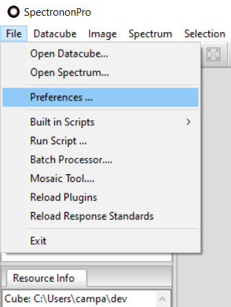
Many advanced data acquisition settings in Spectronon are available by opening the Preferences window from the Main menu by selecting .
4.1. Imager Controls
Your Pika imaging spectrometer can be controlled from two locations: the Imager tab in the Tools panel of the main window (frequently used settings only), and the Preferences window (full settings).
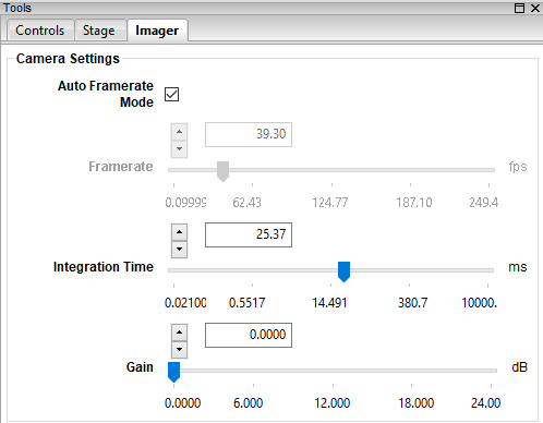
Imager tab in Tools panel of Main window
Open the Preferences window and select the Imager tab. The options for different imager models vary (Pika UV, Pika L, Pika XC2, Pika IR, Pika IR+, Pika IR-L, Pika IR-L+).
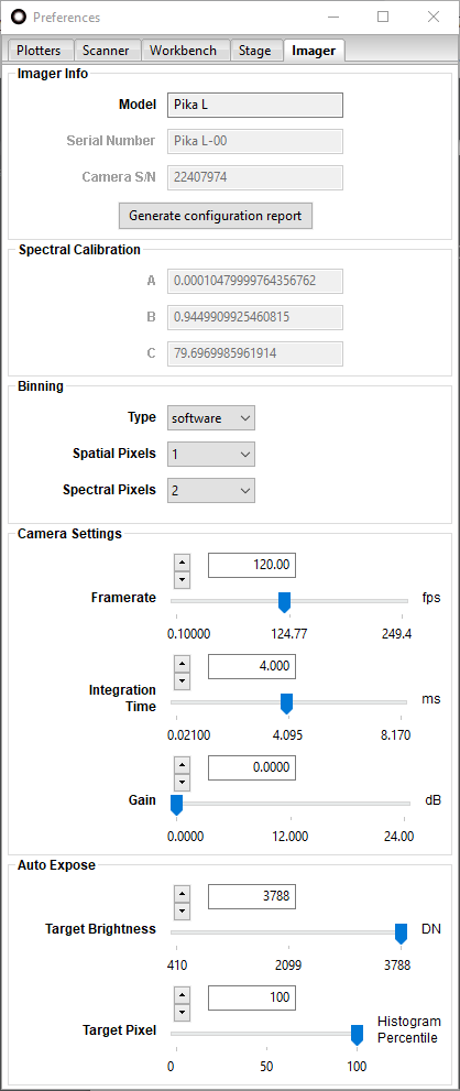
Imager tab for a Pika L in Preferences window
4.1.1. Imager Info
This group provides basic information about your Resonon imager, such as model and serial number(s). The Generate configuration report button generates text-formatted snapshot of your imager’s configuration for future reference, support, or communications with Resonon.
4.1.2. Spectral Calibration
This section lists coefficients used to calibrate your imager. For most Resonon imagers, calibration coefficients are stored in non-volatile memory on the imager itself, and do not need to be modified after they are set by Resonon. See Section 3.3: Verifying Imager Calibration, for additional details. The values are additionally provided on a paper calibration sheet with your imager. Contact Resonon support if you have lost your spectral calibration values.
4.1.3. Binning
The binning (adjacent channel summing) of spectral data can be useful for reducing data size, increasing signal-to-noise ratios, or increasing scanning speed. All Resonon hyperspectral imagers support software binning, and some support hardware binning as well.
The binning Type control selects the binning type, software or hardware (when available). The advantages of each of these binning methods is explained below.
If software binning is utilized, full frames are read off the imager and then adjacent spectral and/or spatial channels are summed in software, producing a frame of reduced spectral/spatial size inversely proportional to the binning factors. If enough light is available to nearly saturate each unbinned pixel (filling the well of the pixel), this technique has the advantage of increasing the effective well depth by the binning factor. This improves the signal-to-noise ratio and dynamic range of the data.
Hardware binning occurs within the camera electronics before a frame is read. It does not improve the signal to noise like software binning does, but it is useful to increase the maximum frame rate of an imager for higher speed scans, such as in airborne applications, where spatial resolution is directly dependent on frame rate.
The Spatial Pixels option indicates how many adjacent spatial pixels to bin. This option is typically useful when imaging an object known to be largely homogeneous, so that the spatial resolution is higher than needed. This also reduces the size of the datacubes.
The Spectral pixels option indicates how many spectral channels to bin. When native spectral resolution is higher than needed, this is your best choice to reduce the size of the datacubes.
Note
The binning options listed above sum the binned pixels, so binned and un-binned data will have different scales.
Available settings vary between imager models and are not available for some imager types.
Imager |
Pika L |
Pika XC2 |
Pika UV |
Pika IR |
Pika IR+ |
Pika IR-L |
Pika IR-L+ |
Max Frame Rate, software binning (fps) |
249 |
121 |
111 |
520 |
249 |
364 |
176 |
Max Frame Rate, hardware binning (fps) |
249 |
165 |
142 |
N/A |
N/A |
N/A |
N/A |
How to choose: The first step is to determine whether to use binning in any form. In the spectral dimension, this will be likely determined by the smallest spectral features of the object wished to be resolved compared to the spectral resolution of the imager. If binning is determined to be allowable, it has the advantage of reducing data size, increasing the signal-to-noise of the data, and/or increasing scanning speed, and should be used.
Spatial binning can also be used but typically spatial resolution is too important to compromise. For some imagers, spatial binning does not impact maximum frame rate the same way as spectral binning does.
If scanning speed is unimportant or there is an excess amount of light present, software binning has the advantage of increasing the signal to noise ratios of the data. If scanning speed is important, hardware binning should be explored to increase imager frame rates. It should also be noted that data can always be binned in post-processing to obtain the SNR benefits of software binning.
4.1.4. Camera Settings
These settings are also available in the Imager tab in the Tools panel in the Main window and were described in Section 3.4: Imager Controls.
Hint
When adjusting the camera settings, you may observe the effects of your adjustments in live view. To do this,
click on the Focus  button.
Note
If you observe broken or torn images when recording data at high framerates, you may be able to eliminate this problem by reducing the framerate. These errors may occur due to limitations in the hardware of the computer, including disk-write speed, chipset, motherboard bus speed, CPU speed, and available RAM.
4.1.4.1. GigE Connection Setup
Resonon’s imagers with GigE connections require that your network adapter be configured to use jumbo packets. If you purchased your computer from Resonon, these steps may have already been completed for you.
To access the network adapter configuration in Windows, click the start menu and type “Device Manager” Click on Device Manager. In the left column, click on Network Adapters in the middle column, right click your wired network adapter, and choose Properties. In the Advanced tab, click Jumbo Packet and set the Value to ~9014 Bytes. Click OK and close the Device Manger window.
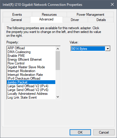
Device Manager - Network Adaptor - Jumbo Packets
Resonon’s Basler GigE imager requires further settings to be configured. In the Advanced tab of Properties window, you also need to find:
Interrupt Moderation: set to Disabled
Interrupt Moderation Rate: set to Off
Receive Buffers: 2048
Lastly, under the Power Management tab, uncheck the option that reads “Allow the computer to turn off this device to save power.”
Note
If these options are unavailable, the Basler GigE will most likely not function properly. Please contact Resonon support (support@resonon.com) for further assistance.
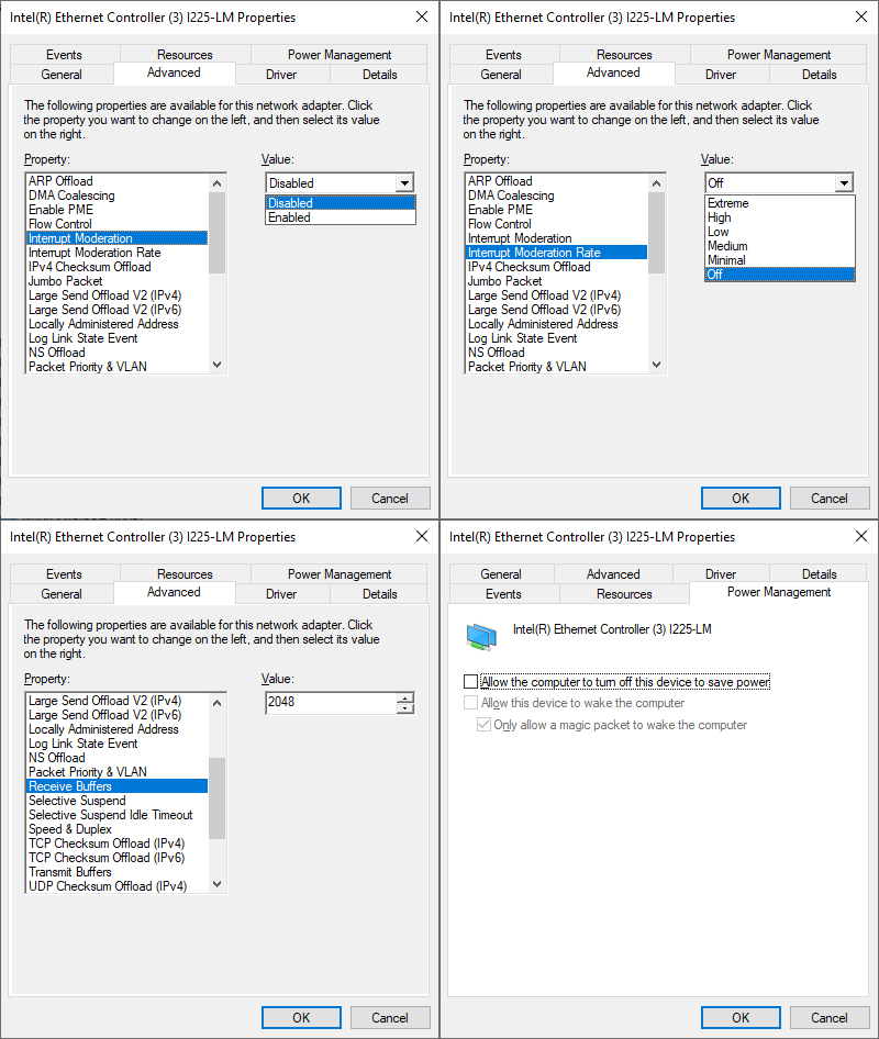
Device Manager - Network Adaptor - Basler GigE settings
4.1.5. Auto Exposure Parameters
Spectronon features a user-configurable auto exposure algorithm that can be controlled in the Imager settings tab. Two parameters are available: Target Brightness and Target Pixel. During the auto exposure routine, Spectronon calculates the histogram of pixel brightness of each frame. For a user-specified (fixed) Framerate, it then iteratively adjusts the Integration Time setting such that the histogram percentile represented by the Target Pixel parameter is at least as bright as the Target Brightness, but is not saturated. If the imager’s camera supports Auto Framerate Mode, then this feature can be turned on to have Spectronon automatically select the fastest Framerate as the auto exposure routine searches for an appropriate Integration Time from the camera’s full range.
For example, if the Target Pixel is equal to 100% and the Target Brightness is equal to 3890 (the default settings for 12 bit cameras), the algorithm will attempt to find an exposure time such that the brightest pixel has a brightness of at least 3890 but less than 4095 (saturation). Similarly, if the Target Pixel = 95%, the pixel that represents the 95th percentile of total brightness will be targeted in each frame, instead of the brightest pixel. Selecting a Target Pixel less than 100% may cause the brightest pixels to be saturated, but may be useful for achieving desired exposure when features of interest are not the brightest in the field of view. For cameras whose detectors do not typically have “hot (saturated) pixels”, Target Pixel is set to 100% and Target Brightness is set to 95% of the camera’s bit depth by default.
4.2. Stage Controls
The stage can be controlled from two locations: the Stage tab in the Tools panel of the main window (most frequently used settings), and the Preferences window (full settings).
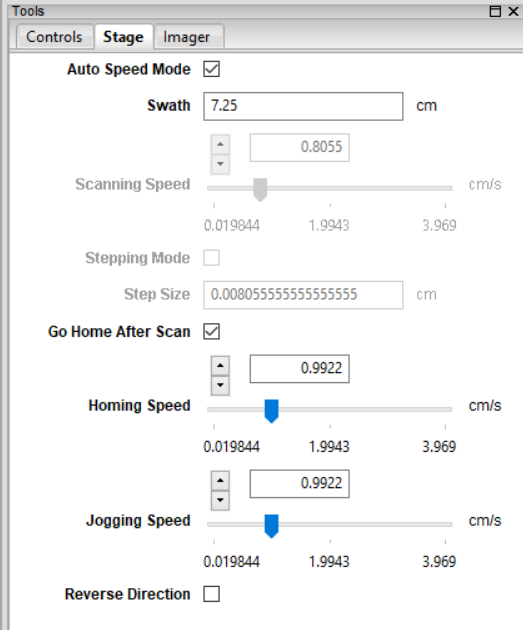
Stage tab in Tools panel of Main window
Open the Preferences window and select the Stage tab.
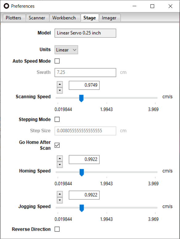
Stage tab in Preferences window
The stage is typically operated with Auto Speed Mode active, which means that the Scanning Speed updates automatically when the imager camera’s Framerate changes. When not in this mode, you have the freedom to customize all of the aforementioned settings.
The following advanced stage settings are available in addition to those described in Section 3.5: Stage Controls.
4.2.1. Model
This indicator provides information about the specific model of stage, including the stage’s screw pitch in mm (or inches) per revolution.
4.2.2. Units
For the Benchtop System, the stage settings use linear (cm) units. For the Outdoor Field System, the stage settings use rotation (deg) units. Spectronon determines the options automatically from the connected stage.
4.3. Additional Controls
Additional settings are available in other tabs in the Preferences window, as well as in the menus of the Main window.
4.3.1. Scanner Preference Tab
The Scanner tab in the Preferences window provides additional options for scanning datacubes.
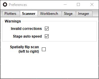
Scanner tab in the Preferences window
The Warnings options allow you to suppress the reporting of certain checks that Spectronon performs before taking each scan. These warnings may be alternatively disabled by clicking “don’t show this again” when they are displayed.
The Spatially flip scan (left to right) option flips the data orthogonally to the scan direction.
4.3.2. Workbench Preference Tab
The Workbench tab in the Preferenes window provides additional options for analyzing, displaying, scaling, and saving datacubes.
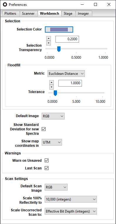
Workbench tab in the Preferences window
The Selection options relate to visualizing selected regions of datacubes.
Default Image determines whether to visualize your existing datacubes as a Red Green Blue (RGB) composite or single band greyscale image upon opening.
Show Standard Deviation for new Spectra toggles the display of +/-1 standard deviation shaded bands for mean spectra computed from multi-pixel selections.
For datacubes with map coordinates, Show map coordinates in selects the units.
The Warnings options determine which warning dialogs are triggered for unsaved datacubes. When checked, the Warn on Unsaved option shows a warning message if you have not saved your last scan before closing the software. Similarly, the Last Scan option warns you if you have not saved your last scan before it is overwritten by a new scan.
The Scan Settings options affect how new datacube scans are processed. The Default Scan Image option determines whether to visualize your new scans as Red-Green-Blue (RGB) composites or single band greyscale images. This setting does NOT impact the hyperspectral data itself; it only changes how the image of the data is presented in the image panel.
The Scale 100% Reflectivity to option allows you to record reflectance data scaled to 1.0 (floats), 10,000 (integers), or Effective Bit Depth (integers). This saves your data as a standard reflectance value IF you use a reflectance reference with a reflectivity of 1. (Spectralon® and Fluorilon® are good materials for this, and Teflon® is a less expensive and reasonable substitute reference material, although less accurate.) Two-byte unsigned integer data is ensured by selecting 10,000 (integers), which also provides reasonable dynamic range. If you use the 1.0 (floats) option, then each channel of data will require 4 bytes instead of 2 bytes. Thus, the size of your datacube will double with this option as compared to 10,000 (integers). The Effective Bit Depth (integers) scales the datacube to the effective bit depth, which is the hardware bit depth of the imager’s camera (e.g., 12-bits, or 4095, for the Pika L, XC2, and UV and 14-bits, or 16,383, for the Pika IR, IR+, IR-L, and IR-L+), combined with any increase from software binning of pixels in the spatial and/or spectral dimension(s), which may require a 4-byte unsigned integer to be properly accommodated.
The Scale Uncorrected Scan to option allows you to scale the raw data taken with your imager to Effective Bit Depth (integers) or 1.0 (floats). We recommend using the Effective Bit Depth (integers) unless you require the other option.
Note
The use of “uncorrected” above refers to the user not using the Dark Current  or Response Correction
  tools prior to collecting a datacube. You would do this if you
wanted to collect raw data and convert it to Radiance using radiometric calibration data provided by Resonon. Prior to
converting, raw data is in digital number (DN).
tools prior to collecting a datacube. You would do this if you
wanted to collect raw data and convert it to Radiance using radiometric calibration data provided by Resonon. Prior to
converting, raw data is in digital number (DN).
4.3.3. Spectrometer Menu
The menu provides alternative approaches to useful actions, as well as some time saving options.
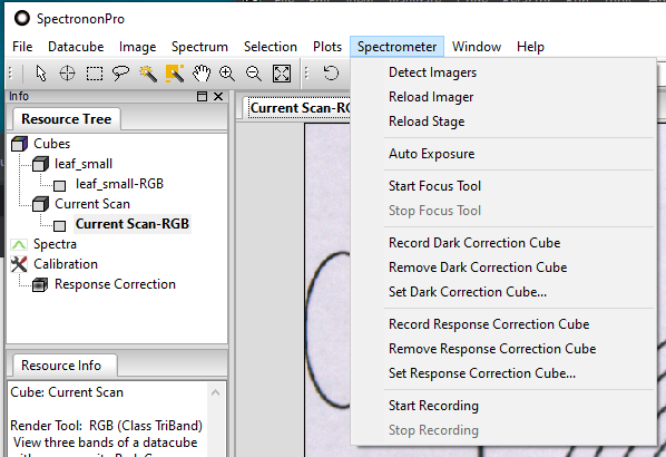
Spectrometer menu on main window
initiates a search for connected imagers, allowing you to detect an imager that was not plugged in when Spectronon was initially opened.
attempts to reload the Pika hyperspectral imager without restarting Spectronon. This option will save you time if you have, for example, accidentally disconnected your imager.
reloads your scanning stage without restarting Spectronon. This option saves you time if you have, for example, accidentally disconnected your stage.
automatically sets the integration time for your
lighting conditions according to the settings discussed in
Section 4.1.5: Auto Exposure Parameters.
You can also start autoexpose with the Exposure button  from the toolbar.
provides a live view from your imager in the Image
panel in the Main window. This tool is useful for adjusting the focus of your objective lens,
checking the illumination of your system, or estimating the swath width along the stage. You can also start
the focus tool by clicking on the Focus button on the Spectronon toolbar.
turns off the live view, which you need to do before you record a
scan. The last live view will remain in a tab of the Image panel in the Main window. Another way to turn
off the live view is to click the Focus button , which toggles live view off and on.
records a dark current cube. The mean frame of this
cube is subtracted from subsequent scans. The presence
of a red check on the Dark Correction button  indicates whether
a dark correction cube is active. When you select this option you will be
instructed to block all light from entering the imager’s objective lens and then click OK. Another way to do
this is with the Dark Correction button on the Spectronon toolbar.
indicates whether
a dark correction cube is active. When you select this option you will be
instructed to block all light from entering the imager’s objective lens and then click OK. Another way to do
this is with the Dark Correction button on the Spectronon toolbar.
removes the dark current correction cube. The presence
of a red check on the Dark Correction button indicates whether
a dark correction cube is active.
sets the dark current correction cube from a file.
records a datacube of a reference material against which
all subsequent measurements will be scaled. Typically this is done with a reference material whose reflectivity is approximately
equal to 100%. When you select this option, you will be instructed to place a reference material filling the imager’s field
of view, and then click on OK. A small response correction datacube will then be recorded and its average
used for scaling the data as described above. The presence of a red check on the Response Correction Cube
button  indicates whether a white reference cube is active. Another way to perform this function
is to use the Response Correction Cube button on the Spectronon toolbar.
indicates whether a white reference cube is active. Another way to perform this function
is to use the Response Correction Cube button on the Spectronon toolbar.
removes the existing response
correction cube. The presence of a red check on the ResponseCorrection Cube
button indicates whether a white reference cube is active.
sets the white reference cube from a file. This option is rarely utilized, as one should generally record a correction cube regularly and with the current lighting to obtain accurate results.
and start and
stop, scans. This can also be done using the Scan button
 on the Spectronon toolbar. The Scan Button toggles between Start and Stop functions
depending on the scanning state.
on the Spectronon toolbar. The Scan Button toggles between Start and Stop functions
depending on the scanning state.