
3. Benchtop System Assembly
3.1. Assembly of Stage, Tower, and Lighting
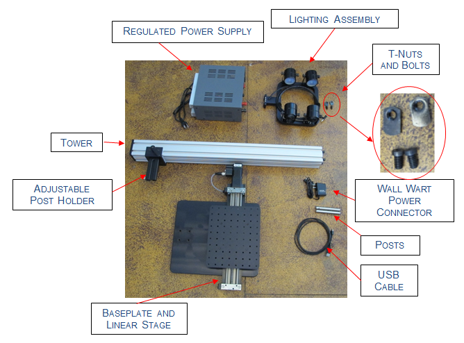
Begin system assembly by removing all items from the shipping package. Confirm that the items shown in the images below. If you are missing components, please contact Resonon.
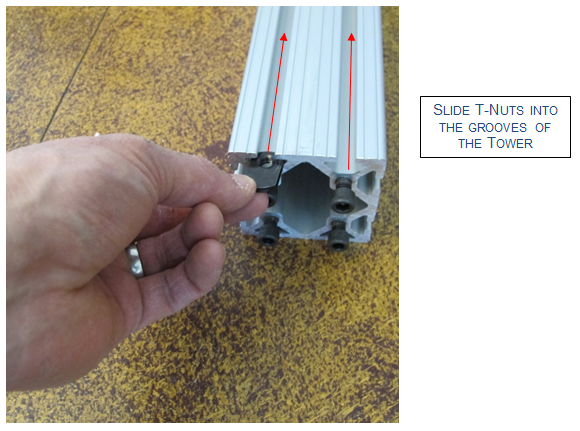
Install lighting onto the tower. Begin by sliding the T-nuts into the slots on the tower. Slide in one T-nut into each slot on the same side as the adjustable post holder.
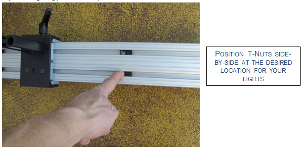
Position the T-nuts side-by-side at the location you wish to attach your lights. (Note: You may easily adjust the lighting position later.)
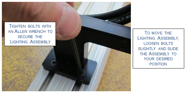
Place the lighting assembly on the post such that the mounting holes line up with the T-nuts.
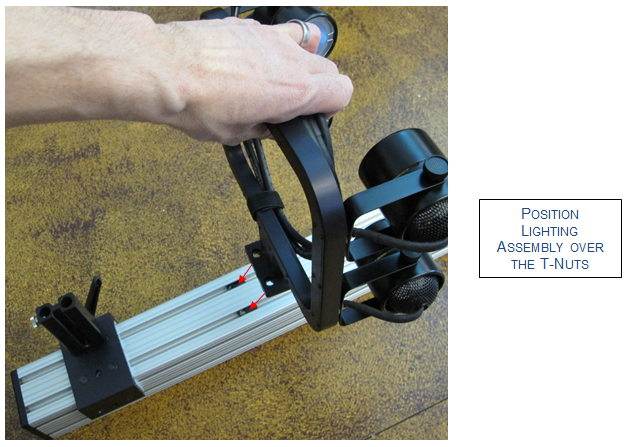
Attach the lighting assembly to the T-nuts using the supplied bolts.
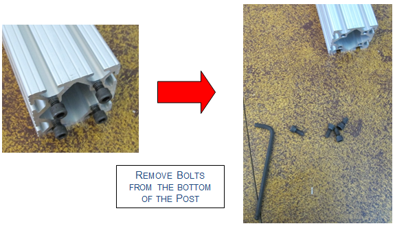
Next, attach the post to the baseplate. Begin by removing the four bolts from the bottom of the post.
Align the post to the baseplate, then tip the baseplate up and attach using the four bolts just removed from the bottom of the post.
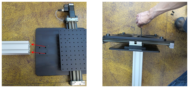
After tightening all four bolts, tip the tower upright.
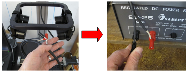
Connect the lighting assembly to the regulated power supply.
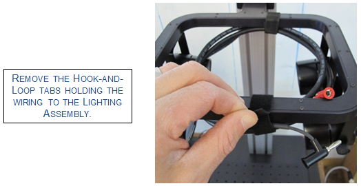
Take the red and black banana plugs, and insert them into the red and black connectors on the regulated power supply.
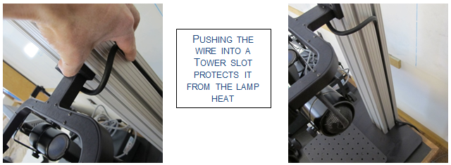
Push the wire into a slot on the side of the tower.
Plug the regulated power supply into a 120 V socket and turn on to test the lighting. Turn the lights off after testing to continue with assembly.
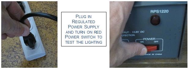
If the lights do not turn on, turn off the red power switch and check all connections. If the lights continue to fail, contact Resonon.
Note
When illuminating your sample with Resonon’s lighting system, allow 20 minutes for the lighting to fully stabilize.
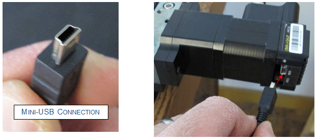
Using the supplied USB cable, connect the stage to your computer. Plug the cable into a black USB 2.0 port, not a blue USB 3.0 port.
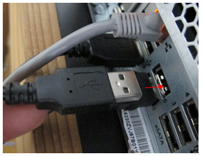
Plug the mini-USB connector end into the stage motor.
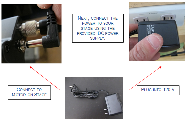
Next, connect the power to the stage using the provided DC power supply.
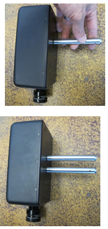
Screw the posts onto the bottom of your Pika imaging spectrometer. The studs in the posts are ¼”-20. Install both posts in neighboring mounting holes on the bottom of the imaging spectrometer.
Insert the posts into the adjustable post holder on the tower.
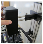
Tighten setscrew on the adjustable post holder to secure your Pika imaging spectrometer.
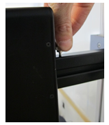
To adjust the height of your Pika imaging spectrometer, loosen the handle on the side of the adjustable post holder, move to your desired position, and then re-tighten the handle.
Assembly of your linear scanning stage system with stabilized lighting assembly is now complete.
3.2. Setup of Hyperspectral Imager
3.2.1. Connecting Pika imaging spectrometer
All Pika imaging spectrometers must be interfaced to a computer for data acquisition. Depending on which Pika imaging spectrometer you have, this interface may utilize a USB or CameraLink interface. Additionally, some Pika spectrometers require external power. The image below shows interfacing with USB 3.
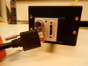
Using the provided interface cable, connect your Pika imaging spectrometer to the appropriate port on your computer.
3.2.2. Installing Calibration Values
Older Pika imaging spectrometers required the user to manually insert calibration values into SpectrononPro software. This is now done during factory set-up of the imager and requires no additional attention from the user. However, your Pika’s calibration numbers are provided on a sheet that comes with your imaging spectrometer and should be checked prior to use. If you cannot locate your calibration numbers, contact Resonon at: ProductSupport@resonon.com.
Connect your Pika imaging spectrometer to your computer. Launch SpectrononPro by double-clicking on the SpectrononPro icon ![]() , or navigate to it from your Start menu.
, or navigate to it from your Start menu.
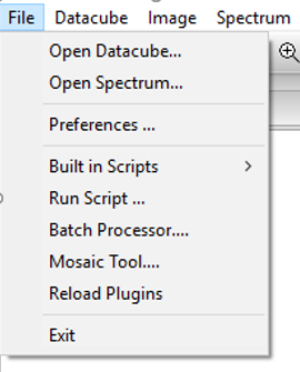
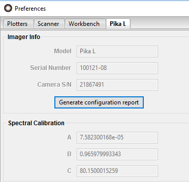
From the Main menu, select File  Preferences… This will reveal the Preferences menu. Select the tab for your Pika imaging spectrometer.
Check the A, B, and C, Spectral Calibration values from the sheet provided against those that are installed in SpectrononPro. If they are different please contact Resonon at: ProductSupport@resonon.com.
Initial setup is now complete. Instructions for how to collect hyperspectral images are given in the chapters on data acquisition.
3.2.3. Objective Lens Installation
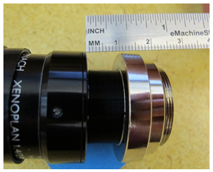
Resonon imaging spectrometers are designed to operate with Schneider c-mount lenses. To install the Schneider lens, first remove the lens and imager from their packaging. Unlock the set screw on the chrome lens collar of the Schneider lens with a 2 mm hex wrench. NOTE: Do NOT remove the screw all the way, just loosen it a few turns.
Holding onto the objective lens by the chrome collar, unscrew the black lens barrel out until there is approximately a 10mm gap between the barrel and collar.
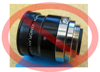
Do NOT install the lens onto the imager if the barrel is screwed in too far as shown below.
While holding and squeezing the chrome collar, thread the objective lens onto the imager.
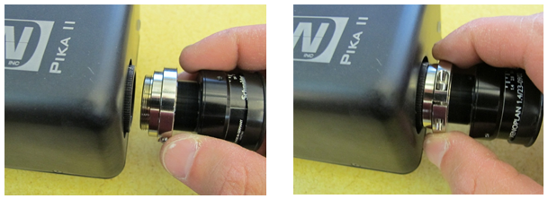
The objective lens is now installed.
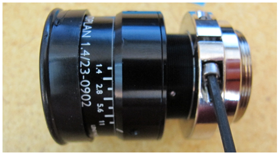
3.2.4. Setting Objective Lens Aperture
Next, set the f-stop (f/#) of the objective lens. There is a range of acceptable options and the end user will need to choose the appropriate value based on his or her application. Large f/#s will provide large depths of field, but limit the amount of light collected, whereas small f/#s will have small depths of field but will exhibit better light gathering.
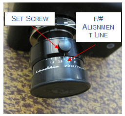
To set the f/# on Schneider lenses, for example, loosen the setscrew on the objective lens itself. This will allow you to rotate the f/# collar on the objective lens, which can be read by noting the location of a small white alignment line. Align the white line with your desired f/#, then retighten the setscrew.
Acceptable f/#s
| Pika L | 2.4 and larger |
| Pika XC2 | 2.4 and larger |
| Pika NIR | 1.8 and larger |
| Pika NUV | 2.4 and larger |